Our goal is to proactively provide our customers with information that will help them be successful. If you have additional questions, please contact us at SCIService@sputteringcomponents.com.
A thin film is a metal or metal-ceramic layer of material that is deposited, atom-by-atom, on the surface of a substrate. The thin film forms a bonded layer that changes the part's appearance, durability or function. 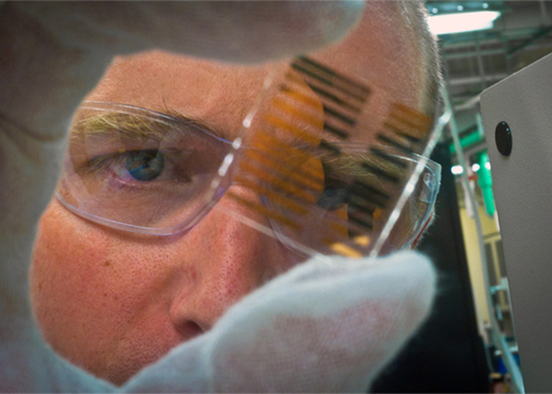
Thin films don't affect dimensional tolerance or the substrate's desired textures. They are used to improve a product's color, light reflection or refraction, hardness or electrical insulation and conductance.
Thin film thickness ranges from fractions of a nanometer (1 nm = 0.000000001 m = 10 angstroms) to several micrometers (1 μm = 0.000001 m). For reference, the diameter of a human hair ranges from 17-181 μm. A strand of spider web silk has a width of 3 to 8 μm.
The controlled synthesis of materials as thin films (a process referred to as "deposition") is a crucial need in many industries. For example, architectural glass, displays, touch panels and solar cells all contain thin films. A familiar example is a mirror, which typically has a thin metal coating on the back of a sheet of glass to form a reflective interface.
Two basic methods are used to create thin films: 1) Chemical deposition, where a fluid precursor undergoes a chemical change at a solid surface and 2) Physical deposition, which uses mechanical, electromechanical or thermodynamic means.
A type of physical deposition is physical vapor deposition (PVD), which occurs in a vacuum. Sputtering is a type of PVD.
Also known as vacuum deposition or vacuum coating, physical vapor deposition (PVD) is a process where source material starts from a condensed phase and then transports through a vacuum or low pressure gaseous environment in the form of vapor (plasma). The vapor then condenses on a substrate to produce a thin film coating.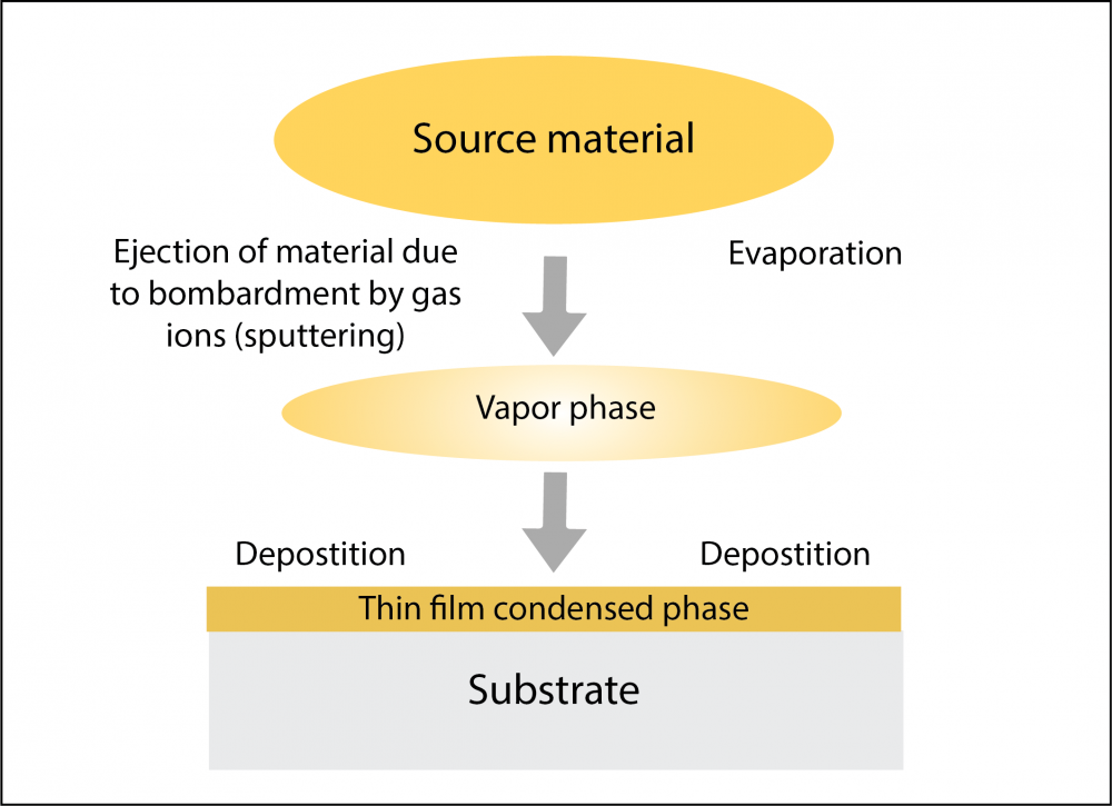
PVD is a physical process, not a chemical process. The most common types of PVD are 1) evaporation, where heated source material evaporates and then condenses on to a substrate and 2) sputtering, where source material is bombarded by gas ions, causing molecules to eject on to a substrate.
Sputtering (sputter deposition) is a method used to create thin films and is a type of physical vapor deposition. Unlike some other vapor deposition methods, the material does not melt. Instead, atoms from the source material (target) are ejected by momentum transfer from a bombarding particle, typically a gaseous ion.
Process sequence: In the basic, single cathode gaseous ion sputtering configuration, the sputtering process sequence is as follows:
- The substrate that will be coated is set inside a vacuum chamber. Air is removed from the chamber, and an inert gas is pumped in at low pressure. Inert gas is used because it does not react chemically to the target material. The most common (and cheapest) sputtering gas is argon (Ar), followed by krypton (Kr), xenon (Xe), neon (Ne) and nitrogen (N2).
- For efficient momentum transfer, the atomic weight of the sputtering gas should be close to the atomic weight of the target, so for sputtering light elements neon is preferable, while for heavy elements krypton or xenon are used.
- Light atomic weight gases such as hydrogen (H) and helium (He) result in negligible sputtering. - Voltage is applied to the target (the material that will be deposited onto the substrate), making it a cathode (negatively charged). The positive anode is the chamber body, which acts as the ground.
- The voltage causes free electrons to flow from the negatively charged target material and collide with the outer electronic shell of the inert gas atoms. The free electrons drive electrons off the inert gas due to their like charge. The inert gas atoms become positively charged ions.
- The inert gas ions attract to the negatively charged target material. During a collision cascade, this attraction ultimately causes inert gas ions to strike the target at an extremely high velocity.
- The bombarding ions have sufficient force to dislodge and eject (sputter off) atoms from the face of the target. The atoms from the target cross the vacuum chamber and are precisely deposited in a typical line-of-sight cosine distribution on the substrate surface as a thin film of material.
- The glowing “plasma” is created when the inert gas ions recombine with free electrons into a lower energy state. The excess energy is emitted as light.
Methods: The basic sputtering methods are planar magnetron, cylindrical magnetron, high-power impulse magnetron, diode and ion beam sputtering.
Advantages: An advantage of this process is that sputter-ejected atoms have kinetic energies significantly higher than evaporated materials for better adhesion. Sputtering can be performed bottom up or top down. Another advantage of sputter deposition is that even materials with very high melting points are easily sputtered.
Applications: Sputter deposition is used in the following commercial applications:
- Architectural and anti-reflective glass coating
- Solar technology
- Display web coating
- Automotive and decorative coating
- Tool bit coating
- Computer hard disc production
- Integrated circuit processing
- CD and DVD metal coating
Please watch our YouTube video for more information about sputtering:
Sometimes called "the fourth state of matter," plasma is one of the four fundamental forms of matter that commonly exist. The other three are solid, liquid and gas. 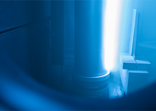
Plasma contains ions, free radicals, neutral byproducts, and photons. Plasma can be created by heating a gas or subjecting it to a strong electromagnetic field. This decreases or increases the number of electrons, creating positively or negatively charged atoms or molecules called “ions.”
With plasma, positively charged nuclei swim in a "sea" of freely-moving disassociated electrons, similar to the way such charges exist in conductive metal. This electron "sea" allows matter in the plasma state to conduct electricity.
Like a gas, plasma does not have definite shape or volume. Unlike gases, however, plasmas are electrically conductive, produce magnetic fields and electric currents, and respond strongly to electromagnetic forces.
The plasma state, although less understood, is quite common. Lightning, electric sparks, fluorescent lights, neon lights, plasma televisions and some types of flame are all examples of illuminated matter in the plasma state.
While conventional cathode sputtering can deposit extremely thin films down to the atomic scale, it tends to be slow and most effective only with small substrates. The bombardment of the substrate can also create overheating or damage to the object to be coated.
With magnetron sputtering, magnetic fields increase plasma density for a higher deposition rate and a more efficient process.
Magnets (usually permanent magnets) behind the cathode confine electrons over the negatively charged target material, enhancing both the efficiency of the initial ionization process and allowing plasma to be generated at lower pressures.
The lower pressure reduces both background gas incorporation in the growing film and energy losses in the sputtered atom through more gas collisions since electrons follow helical (spiral) paths around magnetic field lines. The longer paths mean a higher probability of ionizing collisions with gaseous neutrals near the target surface than would otherwise occur.
The result is very dense plasma and a higher deposition rate. The sputtered atoms are neutrally charged and are unaffected by the magnetic trap.
Following the shape of the magnetron, the target material is consumed in an oval shape, called a "racetrack."
Operating voltage decreases with increased magnetic field strength. Both direct current (DC) and radio frequency (RF) power sources can be used with most magnetron cathodes. Pulsed DC and low and mid frequency power supplies are also used in magnetron sputtering.
Magnetron sputtering is the most widely used deposition process to achieve very uniform and smooth thin film coatings. Using large cathodes and arrays of large cathodes, magnetron sputtering is used extensively to deposit large area single layer and multi-layer coatings. Magnetron cathodes are also used in in-line and roll-to-roll processes.
Modern cathodes offer excellent target utilization and high deposition rates. Almost any metallic material can be sputtered. Sputtering magnetrons can be oriented in any position to accommodate equipment design. The target is water cooled to minimize radiation heat.
Sputtering magnetrons can be planar magnetrons or rotating (cylindrical) magnetrons.
A rotary (cylindrical) cathode is a device used for sputtering target material from the surface of a rotating target tube onto a substrate.
A hollow tube of target material rotates around a stationary magnet array suspended inside the tube. This stationary magnet array is directed at the substrate and holds the process plasma in the desired location.
Electric power is transmitted to the rotating target tube. The cathode is the target tube surface since the electrons leave from the target surface and enter the plasma. Cooling water is usually used inside the target tube for sputtering process cooling.
Powered by a motor, an end block rotates the target tube. It has rotary seals for both cooling water and vacuum. While the cathode assembly is mounted to the inside lid of a vacuum chamber, the end blocks can be external to the chamber or inside the chamber.
Please watch our YouTube video for more information about rotary cathodes.
Cost
Lower initial capital investment: The initial capital investment for rotaries is less than typical planar cathodes for 1.5 m systems and larger. Furthermore, when using temperature-sensitive materials, fewer rotary cathodes are needed to coat the same area.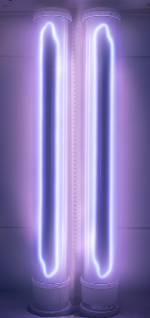
Higher target utilization: Rotary cathode target utilization is characteristically between 70-85 percent versus 25-40 percent with planar targets. This is because the target moves through the stationary plasma and is eroded all around its circumference.
Quality
Less arcing and particle generation: The smaller re-deposition zone surface area on rotary cathodes reduces 1) the probability of particle generation that can end up on the surface of the substrate, and 2) the probability of arcing when sputtering dielectric films.
Reduced nodules with TCOs: Lower target temperatures and more efficient cooling of the target allow rotary cathodes to run at higher power densities than planar cathodes without forming nodules when depositing TCOs such as ITO.
Less process drift: With some target materials, there is less process drift and better films due to lower impedance. Lower impedance is the result of much narrower and stronger magnetic field designs compared to the wider, weaker planar magnetron magnetic fields.
Time
Longer campaign times: Campaign times are longer because most rotary targets have three to four times the sputter material available due to the geometry of the target, Targets life is longer due to higher utilization.
Faster target changes: Changing targets is much faster than with planar systems, especially with most Sputtering Components configurations because all utilities are introduced on one end block. The other end is a simple support.
Shorter burn-in time: Target burn-in time is reduced as there is much less material re-deposition onto the rotary cathodes. Although rotary targets are sometimes ‘burned in’ at the start of a run, planar cathode ‘burn in’ often interrupts production.
Higher deposition rate: For some processes, primarily with materials that are temperature-sensitive, deposition rate is increased because lower impedance and better target cooling allow stronger electrical power.
Reactive sputtering is a type of sputtering where a target of one chemical composition (e.g. elemental Si) is sputtered in the presence of a gas or a mixture of gases (e.g. Ar + O2) that will react with the target material to form a coating of a different chemical composition (e.g. compound SiO2) on the substrate.
The following are commonly used reactive gases:
- Oxygen (O2) – deposition of oxide films (e.g. Al2O3, SiO2, TiO2, HfO2, ZrO2, Nb2O5, AZO, ITO)
- Nitrogen (N2) – deposition of nitride films (e.g. TiN, ZrN, CrN, AlN, Si3N4, AlCrN, TiAlN)
- Carbon dioxide (CO2) – deposition of oxide coatings
- Acetylene (C2H2) – deposition of metal-DLC, hydrogenated carbide, carbo-nitride films
- Methane (CH4) – similar to acetylene
Reactive gases can also be mixed (e.g. O2 + N2) in order to deposit multi-component functional thin films, such as oxy-nitrides (e.g. Cr-O-N) or oxy-carbides (e.g. Si-O-C).
Radio frequency (RF) sputtering is a type of sputtering that is ideal for target materials that have insulating qualities. Like direct current (DC) sputtering, this technique involves running an energetic wave through an inert gas to create positive ions.
RF sputtering needs about nine times more input voltage than DC sputtering because the creation of the radio waves requires more power input to achieve the same effect as an electron current. The plasma can be maintained in lower pressure than DC sputtering. As a result, a more direct pathway for the particles to travel to the substrate material is created by fewer collisions between the target material particles and the gas ions.
Large-area substrates are usually wide flat rigid panels (such as glass or plastic) or wide flexible webs (typically plastic or metal) that are coated as they pass by the stationary magnetrons.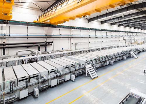
Some examples of products made from these substrates include low-E window glass, solar panels, solar control window tint and flat-panel displays.
You will need to provide four types of connection to your SCI rotary (cylindrical) magnetron:
Cooling water for SCI rotary magnetrons: Provided to the cathode using ¾” or 1” flexible hose, connecting to a hose barb or other customer-specified water fitting. Nominal inlet pressure should be 40 psi, with a maximum of 100 psi. Water flow rates should be 1 liter per minute per kW of applied power, or greater. Water quality should be 100-300 micro Siemens, with 75 micron filtration. Inlet temperature should be less than 30°C and maintained above the ambient dew point to prevent condensation.
Power supply connection for the SCI rotary magnetrons: Various connection styles are provided using M8 or M10 screws. SCI can provide custom length, low impedance cable assemblies, which are optimized to your cathode power rating and mounting pattern.
Drive motors: SCI provides AC inverter duty motors with its end blocks. The inputs to this motor are 230 V, three-phase,10-90 Hz, 480 V is available. Speed control is provided by the use of a customer supplied variable frequency drive (VFD.) The VFD can be selected to accept your local input voltage and number of phases and convert to the motor inputs. SCI can also supply these drives upon request.
Drive encoders: SCI provides an encoder with every end block. The encoder ensures cathode rotation and, if desired, measures rotation speed. The encoder is connected depending upon how it will be used:
- To confirm rotation only: The encoder can be connected to a signal conditioner (such as the Red Lion IFMR0036) that will convert the encoder pulses to a digital signal, which can be used to interlock rotation. SCI can provide these signal conditioners upon request.
- To measure rotation speed: The encoder is a simple 100 pulses per revolution quadrature encoder. The pulses from channel A (and/or B) can be used for speed measurements. The SC/SM cathodes are set to 294 pulses per target revolution while the MC/MM is 235 PPR.
See the user manual for more information.
The length of the target tube is determined by the substrate length and the coating uniformity requirements. SCI refers to the overall length of the backing tube as the basis for calculation as it will define the system geometry. The actual length of the material to be sputtered will be shorter than the backing tube length.
The standard calculation that we use is the following:
Backing Tube Length = Substrate Length + 4 * Target-to-Substrate (TTS) distance
This equation is typically used for TTS distances between 75 to 150 mm. If the application has uniformity requirements higher than +/-2%, we suggest to add additional length to the target in order to reduce the initial uniformity tuning required for rotary-type sputtering cathodes.
SCI will calculate the deposition rates and the number of rotary magnetrons required for your application. Please contact us at SCIService@sputteringcomponents.com.
If you wish to do the calculation yourself, please note the following:
Each target material and coating process has limitations as to how fast the material can be deposited from each magnetron.
Thus each different process has a limited dynamic deposition rate (DDR).These limits for most materials have been experimentally obtained and are correlated with the power density that was applied to the target at the time of the deposition.
Using this information, we create a unit for calculation the normalized dynamic deposition rate (nDDR) that has the units of (nm-m/min)/(kw/m).This unit can be used along with the maximum power density that target vendors recommend using with their targets to figure out approximately what the dynamic deposition rate of each rotary magnetron will be for a particular process.
Desired (or maximum) power density = Power applied from power supply in kW divided by the target tube length in meters -> (kW/m)
nDDR(nm-m/min)/(kW/m) * Desired power density(kW/m) = DDR
DDR / substrate velocity = Coating thickness per magnetron
Number of cathodes required = Target coating thickness / Coating thickness per magnetron
To determine your dynamic deposition rate, multiply the thickness of the coating you want to make in nanometers by the velocity of your substrate in meters per minute.
Example: With SiO2 coating that is 20 nm thick and a substrate speed of 1.5 meters per minute, the dynamic deposition rate is 30 nm * m/min:
20 nm * 1.5 m/min = 30 nm * m/min
To avoid damage and contamination that could cause quality issues during the coating process, use simple precautions to store and handle cylindrical targets: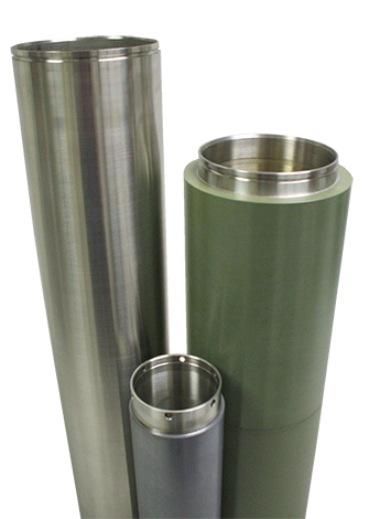
Handling
- Never touch a sputter target surface with your bare hands. Handle targets with plastic or rubber gloves to avoid surface contamination and subsequent problems during sputtering.
- Before lifting the target with a crane or handling it in any way, wrap it in protective paper and a layer of foam.
- Keep the target surface clean at all times and free of dust, water and grease.
Use under vacuum
- When the sputter target is mounted and operating in a substantially horizontal position in the coater, prevent sagging or deformation of the tube by engaging the cooling water system and keeping the target rotating.
- Before the heaters in the coater are turned on, prevent non-uniform thermal loading by engaging the cooling water system and rotating the target.
- Do not stop target rotation and do not shut off the cooling water until the heaters are turned off and the system has cooled.
Storage
- Keep a new sputtering target in its original packaging until it will be used.
- If a target needs to be stored after partial use, re-wrap it in protective paper, foil or foam.
- Store the target in its original crate, which should support the target on both ends and in the middle. Place the crate in dry, dust-free environment.
The number of atoms ejected per incident ion (atoms/ion) is called the sputtering yield, Y. Sputtering yield is dependent on the following:
- Energy of the incident ion
- The incident angle
- The surface binding energy of atoms in the target: for example lead (Pb) will have provide a much higher sputtering yield in comparison to titanium (Ti)
- The masses of the ion and target atoms: momentum transfer is more efficient if the masses are similar.
